NVIDIA GeForce GTX 1080 Ti
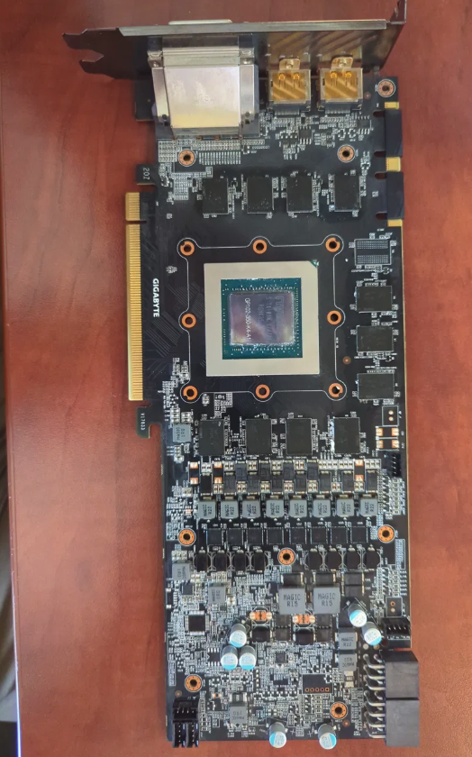
This is a NVIDIA GeForce GTX 1080 Ti, specifically a Gigabyte board, with the cooler/heatsink removed so you're looking at the bare PCB. The dead giveaway is the chip marking in the center: GP102-350-K4-A1. GP102 is NVIDIA's big Pascal-architecture die, and the -350 variant is the one binned for the 1080 Ti (for comparison, GP102-400 was the Titan X Pascal and GP102-450 was the Titan Xp). The "GIGABYTE" silkscreen on the left edge tells you the board partner. One framing note: this is a consumer/gaming card, not a datacenter "node" GPU. The Pascal-era datacenter parts used the GP100 die (Tesla P100) with HBM2 memory and very different packaging. So in the HEP/ML sense, this is the kind of card you'd find in a workstation or a small lab box rather than in a cluster node. Here's what you're looking at, region by region: GPU die (center) — The exposed silicon you see is the bare GP102 die sitting on its green organic substrate. Unlike a CPU, consumer GPUs of this era ship without a metal heatspreader, so the cooler's cold plate contacts the die directly. ~12 billion transistors, 3584 CUDA cores on the full 1080 Ti. Memory chips (dark squares around the die) — These are the GDDR5X modules. The 1080 Ti carries 11 GB across 11 chips on a 352-bit bus (that odd number is why it's 11 GB rather than 12). They're clustered close to the die to keep trace lengths short for signal integrity at high clocks. VRM / power delivery (lower half of the board) — This is the busiest section:
The encapsulated inductors stamped MAGIC R22 and MAGIC R15 are the power chokes (R22 ≈ 0.22 µH, R15 ≈ 0.15 µH). The black rectangular packages just below them are the MOSFETs / power stages that do the actual switching. The cylindrical and small SMD components are the output/input capacitors smoothing the rails. Together this is a multi-phase buck converter stepping the 12 V input down to the ~1 V core voltage, plus a smaller separate phase for the memory.
PCIe edge connector (left edge, gold fingers) — The x16 slot interface; data and a chunk of power come through here. Power connectors (bottom-right) — The supplemental PCIe power inputs (the 1080 Ti reference layout uses 6+8-pin) feeding the VRM, since the slot alone can't supply its ~250 W board power. Ring of holes around the die — The cooler mounting pattern; the sprung X-bracket on the back applies even die pressure. Display outputs (top bracket) — DVI-D, HDMI, and DisplayPort. If you want, I can point out the likely PWM controller or estimate the phase count from the choke layout — happy to zoom into any region you're curious about.
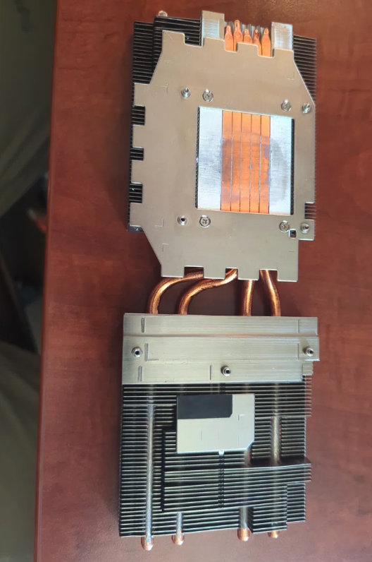
This is the cooler that bolts onto the PCB you showed earlier — and it's a nice example of a heat-pipe-based vapor cooling system. Let me walk through how it actually moves heat off that GP102 die. The cold plate (the copper block in image 1) The bright copper rectangle in the first image is the contact base — the part that presses directly against the bare GPU die through a thin layer of thermal paste. This is the hottest point in the whole system. Its job is to grab heat off a tiny ~1.5 cm² die and spread it out fast enough that the die doesn't cook. You can see the discoloration/paste residue right in the center where it sat on the die. Around it, the silver metal frame also makes contact (via thermal pads) with the memory chips and VRM components, so it cools those too. The heat pipes (the copper tubes) Those U-shaped copper tubes are the clever part, and they're not just solid copper wires — they're heat pipes, which are sealed hollow tubes that move heat far faster than solid metal could. Here's the trick inside them:
Each pipe is sealed and partially filled with a small amount of working fluid (usually water) under low pressure, with a wick (sintered powder or grooves) lining the inner wall. At the hot end (touching the cold plate), the fluid boils into vapor, absorbing a large amount of heat as latent heat of vaporization. The vapor rushes down the tube to the cooler end (out in the fin stacks). There it condenses back to liquid, dumping that latent heat into the fins. Capillary action in the wick pulls the liquid back to the hot end, and the cycle repeats.
This phase-change loop is why a thin copper pipe can shift far more heat than its cross-section suggests — it's effectively a thermal superconductor. You can count the pipes in your photos; this looks like a 4–5 pipe design typical for a ~250 W card. The fin stacks (the dense aluminum slabs) The two big blocks of thin parallel sheets are the radiators. The heat pipes thread through them, and the fins present a huge surface area to the air. In image 2 you can see the pipes fanning out and weaving through both fin towers — splitting the heat load across two separate stacks so neither gets saturated. Aluminum is used here (not copper) because it's lighter and cheaper, and once the heat pipes have delivered the heat, conductivity matters less than surface area and weight. The fans (not pictured) The missing piece is the fan(s) that mounted over these fins, forcing air through the fin gaps. The fins do almost nothing without airflow — they need a constant stream of cooler air to carry the heat away by convection. So the full chain is: die → thermal paste → copper cold plate → heat pipes (boil/condense) → aluminum fins → forced air → out of the case. Each stage hands heat to a progressively larger, cooler medium. The reason for all this complexity is the brutal power density: ~250 W coming off a fingernail-sized die is a heat flux comparable to a stovetop burner concentrated on a postage stamp, so spreading it out aggressively is the only way to keep the silicon under its ~85 °C limit. One thing worth noting for your energy-systems interest: this is exactly the bottleneck that pushes datacenter GPUs toward direct liquid cooling. Air-cooled heat pipes top out around a few hundred watts per card, but modern datacenter accelerators (700 W–1 kW+) exceed what this kind of finned assembly can handle, which is why cold plates with circulating coolant — and now immersion cooling — have taken over at the high end.